Designing a CM5 Carrier Board - A Practical Guide for Makers and Engineers
Creating a custom carrier board for the Raspberry Pi Compute Module 5 (CM5) can seem daunting—but with the right tools and best practices, it becomes a highly rewarding venture. Whether you’re building a robot, a smart display, or an embedded controller, a well-designed carrier board ensures stability, reliability, and full access to CM5’s features.
In this post, we’ll walk through both high-level considerations and practical tips for building your own CM5 carrier board—based on real-world experience and community knowledge.
🔧 Essential Resources to Get Started
Before diving into schematics or layouts, gather these helpful files and templates:
✅ Reference Files
Raspberry Pi Official CM5 IO Board KiCad Files
Download from Raspberry Pi
This gives you a solid reference for pinouts, layout, and component usage.Shawn Hymel’s CM4/CM5 Carrier Board Template
GitHub Repo
Move thehardwarefolder into your KiCad base folder (usually in your Documents) for easy access.
🧠 Schematic Tips & Best Practices
Use Hierarchical Sheets
KiCad lets you split designs into multiple sub-sheets for clarity and modularity. Use labels (especially global labels) to connect signals between sheets reliably.- Library Management
- When adding custom components (e.g., regulators, connectors), download both the symbol (
.lib) and footprint (.pretty) from the manufacturer or Digi-Key. - Add these libraries via Project > Manage Symbol Libraries in KiCad.
- Maintain naming consistency for smooth integration.
- When adding custom components (e.g., regulators, connectors), download both the symbol (
- Component Properties Matter
Update each part’s metadata (Manufacturer, MPN, Digi-Key/Mouser Part Number). These fields will be used when generating the Bill of Materials (BOM).
Tip: “Cut tape” is great for sourcing single units.
⚡ Electrical & Mechanical Design Considerations
🪛 General Hardware
- Power Supply: Provide 5.1V @ 5A via a VIN pin.
- Add a Power LED: Simple, but valuable for diagnostics.
- Screw Mounts: Include at least four mounting holes for mechanical stability.
🔄 eMMC Boot Management
To flash the CM5 when using onboard eMMC:
- Add a solder jumper between the
nBOOTpin and GND to disable eMMC boot. - This enables USB booting via the USB-C port—essential for headless devices.
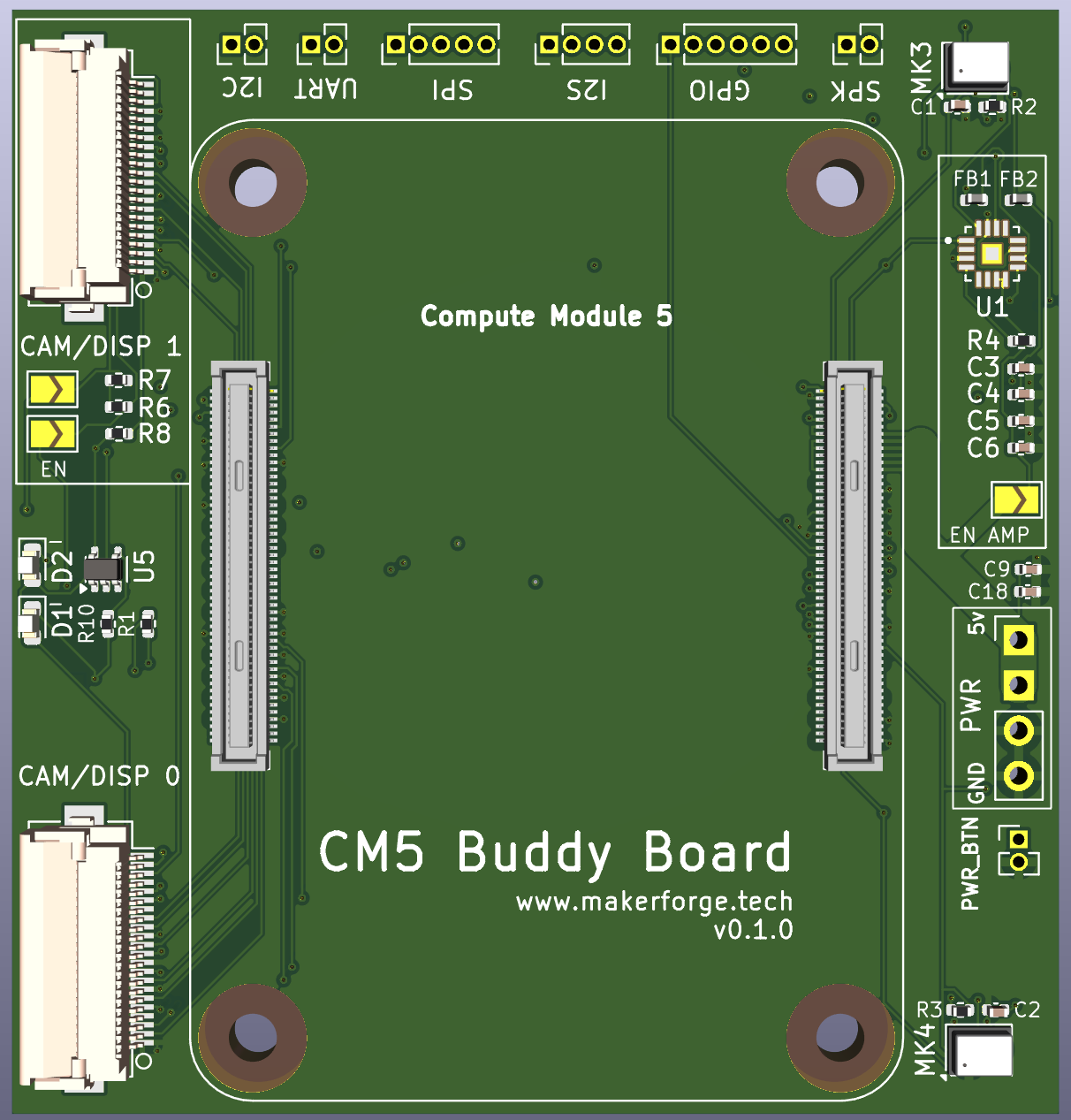
🧩 Interfaces to Expose
| Interface | Pins | Notes |
|---|---|---|
| I2C | GPIO 2 (SDA), GPIO 3 (SCL) | Use pull-ups if needed |
| I2S | GPIO 18, 19, 20, 21 | Audio in/out support |
| SPI | GPIO 8, 10, 11, 25, 27 | Displays, sensors, Neopixels |
| UART | GPIO 14 (TX), GPIO 15 (RX) | Connect GND to complete circuit |
| USB | USB-C (programming), USB-A (peripherals) | One USB-A port is usually enough |
| Camera/Display | CSI, DSI ports | Make both accessible |
| GPIO | 40-pin header | For compatibility with Pi HATs |
📏 Layout & Signal Integrity
🧮 Net Class & Impedance
- Update Design Rules: Set default track width and clearance to 0.2mm to match the fine-pitch CM5 connector.
- USB Data Lines: These require differential impedance.
- Follow a coupled microstrip line design.
- Use tools or calculators (like Saturn PCB) to determine trace width/gap.
- Create a dedicated Net Class in KiCad for USB differential pairs (D+ and D−).
👉 For more detail, check: Octavo Systems USB Design Tutorial
Shawn Hymel’s CM4 Design Video (Part 1)
📌 Additional Layout Tips
- Fiducials: Place two 1mm fiducials in opposite corners to help pick-and-place machines align the board.
- Connector: Use a Hirose connector (the same one used in the CM5 IO board) for CM5 compatibility.
👉 Follow the Discussion
Take a look at this post on the MakerForge GitHub for a community-driven discussion on CM5 carrier board design. It’s a great place to ask questions, share your designs, and learn from others.
🧪 Final Thoughts
Designing a CM5 carrier board is a blend of electrical engineering, mechanical design, and a bit of artistic layout finesse. By using community resources, following standard practices, and taking time to carefully manage signal integrity and component sourcing, you can create a robust platform tailored to your application.
Whether you’re building a robotic platform like the Modular Biped or a custom embedded system, this guide should help you make smart, future-proof design choices.
Happy prototyping!